Posts

Showing posts from March, 2013

Introduction to Alternating Current

Image
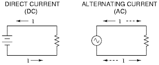
Last time, we studied the first part of Learn Electrical Engineering for Beginners and this is all about DC Circuits . Today, we will be dealing with our Part 2 of our module and this is all about Alternating Current Circuits . So, you may now start to learn what this ac is and how it behaves. Alternating Current does not flow through a conductor in the same direction as what dc does. Instead, it flows back and forth in the conductor at the regular interval, continually reversing its direction of flow and can do so very quickly. It is measured in amperes, just as dc is measured too. Remember, one couloumb of electrons is passing a given point in a conductor in one second. This definition also applies when ac is flowing- only now some of the electrons during that 1 second flow past the given point going in one direction, and the rest flow past it going in the opposite directions. Difference between DC and AC The industrial applications of alternating current are widespread. These includ

Simple Example of Network Analysis

Image
Last time, I have already imparted to you about the theoretical aspects of Network Analysis here in my simple Electrical Engineering educational site. Today, I will just give you some simple example for you to appreciate the last topic I had posted over a year ago. :) Take a look at the simple electric circuits below. If you have a voltage divider with an external resistance, you could do this by using Ohm' Law and calculating the parallel resistance of R2 and R(Load) and then the voltage divider itself. The simpler method that you can use is the Thevenin's theorem which enables you to calculate quickly the effect of any load. Simple Circuit using Thevenin's Theorem Considering you have R(Load) equivalent to 40 ohms is in open circuit condition. We can now calculate the equivalent Thevenin resistance. Therefore, R (Thevenin) = R1R2 / R1+R2 = 20X40/ 20+40 = 13.33 ohms. Also, you can calculate the voltage across R2 at no load using the voltage division method: E(Thevenin)

Output Inductor Calculation for SMPS Converters using the Forward, Push-Pull, Half-Bridge and Full-Bridge Topologies

Image
An output inductor is found at the output of every forward-mode converter. Converters utilizing the forward, push-pull, half-bridge and full-bridge topologies are all forward-mode converters. So, calculation of the output inductance follows the same methodology for all four of these popular topologies. The purpose of the output inductor is to store energy for the load during the time each switching cycle when the power switches (BJTs, MOSFETs or IGBTs) are turned off. The electrical function of the output inductor is to integrate the rectangular switching pulses (pulse width modulated signals with varying duty cycle) into DC. The capacitor following the inductor smooths the DC into clean DC. The design of the output inductor is quite simple. Usually, a self-gapped toroid core is used. Gapped ferrite cores (the ones used for ferrite transformers, eg ETD39) can also be used with no difficulties. The formula for calculating the output inductance is: Vin(max) is the highest peak voltage fo